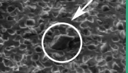
Analysis of cause and solution of edge breakage in Wafer cutting
A wafer goes through three changes before it becomes a real semiconductor chip:
First, semiconductor chip is cut from a lump of ingots into wafers.
In the second step, a transistor is engraved on the front of the wafer by the previous step.
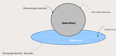
Finally, the wafer is packaged, that is, cut through the process to make a complete semiconductor chip. In this process, the wafer is cut into a number of hexahedral shape of the single chip, the process is called “Singulaton”, and the process of Sawing the wafer into a rectangular shape is called “Die Sawing”.
Wafers are the basic raw materials for the production of semiconductor devices. High-purity semiconductor materials are made into wafers through processes such as crystal pulling and slicing. Wafers produce tiny control circuit structures through a series of semiconductor manufacturing processes, and then through cutting , Packaging, and testing become chips, which are widely used in various electronic instruments.
Wafer chamfering and rounding are usually made of curved cutting or internal dicing saw blades. The outer edges of the cut wafers are particularly sharp. In order to prevent the cracking of the corners from affecting the hardness of the wafer, or damaging the surface finish and subsequent processes Bringing environmental pollution, it is necessary to automatically correct the edge, shape and outer diameter of the wafer with special numerical control equipment, so the wafer dicing saw balde directly affects the quality of the finished product.
1. Wafer cutting mainly uses wafer dicing blades
2. Wafer surface chipping can be divided into three types: initial chipping, repeated chipping, and other chipping.
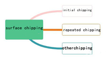
wafer cutting
1. Initial chipping
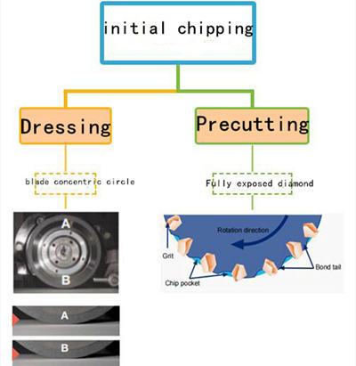
It mainly refers to the product surface collapse in the pre-cutting stage of new blade installation, which may be caused by three aspects:
① The blade is tilted.
② The blade is not rounded.
③ The diamond is not completely exposed, and there is no capacitive grooves.
Solution of initial chipping:
(1) Check the grinding dicing blade installation accuracy.
(2) Repair the grinding dicing blade, trim the concentricity of the blade.
(3) Reprecut to fully expose the diamond.
2. Repeated chipping
The reason of repeated chipping:
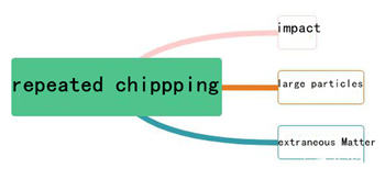
There are three main reasons for repeated cyclic edge collapse in the cutting process:
1. The grinding dicing blade surface is impacted.
2. Large diamond protrusions on the surface.
3. The diamond Dicing Blades surface is adhered by other foreign impurities.
Solution of repeated chipping:
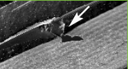
1. Check whether the surface has the impact mark of product flying material.
2. Observe whether there is large particle protuberance in the blade part under the microscope.
3. Observe the blade surface under a high power microscope whether there are foreign bodies (such as residual glue, metal).
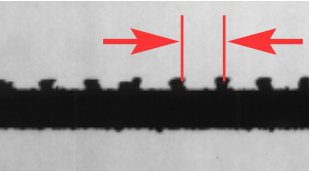
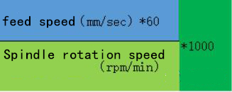
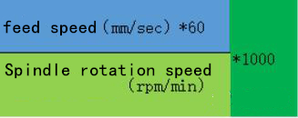
The picture and calculation formula of edge collapse in repeated regular interval are as follows:
Regular interval edge breakdown diagra Calculation formula of edge breakage Observation under microscope: impact of flying material
Microscopic observation: large particles Observation under microscope: extraneous Matter
3. Other chipping
The reason of other chipping:
There are three main reasons for abnormal edge collapse in the cutting process:
1. The workpiece is displaced and deformed
2. Feed speed and cutting depth
3. High speed blade deflection
Solution of other chipping:
1. Increase the baking temperature and time after laminating and replace the base material
2. Adjust the appropriate processing parameters according to the workpiece material
3. Test the accuracy of equipment spindle and blade dynamic balance
2. Back side chipping
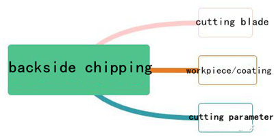
1. There are three main investigation directions after back collapse:
2. The cutting blade
3. Workpiece/fixed film
4. The processing parameter
There are strong correlation factors between wafer back breakage and blade:
1. The size of the back edge of the blade before precutting is larger than that after precutting.
2. The larger the diamond particles of the blade are, the smaller the chip size on the back is.
3. The lower the abrasive concentration of the blade, the smaller the back edge breakage size.
4. The softer the cutting blade binder, the smaller the back edge breakage size.
5. The thinner the cutting blade, the smaller the back edge.
Solution :
1. Use the cutting blade repair board to repair the new knife and perform pre-cutting.
2. Select a blade with appropriate mesh size as the cutting blade (3000-3500 mesh is recommended).
3. Select a blade with a low concentration as the cutting blade (50-70 recommended).
4. Select a soft binder formula as the cutting blade.
5. Select a thin blade as the cutting blade.
There are three strong correlation factors between wafer back breakage and fixed consumables:
1. Fixing method (paraffin wax, adhesive film, fixture)
2. The fixed force
3. Fixed auxiliary material (thickness of adhesive layer, thickness of substrate, hardness of substrate)
Solution:
1. Wafer cutting selection of strong viscosity, thin adhesive layer, substrate elasticity of small blue film or UV film
2. Keep the ceramic pores on the surface of the cutting disk without blockage, the vacuum suction is uniform, and the working disk is flat
There are four strong correlation factors between wafer back breakage and processing parameters:
1. Spindle speed, spindle speed is too high, the amount of each abrasive particle is reduced, but the self-sharpening ability of the blade is inhibited, and passivation may occur.
2. The feed speed, the feed speed is too high, will increase the load of the blade, the stress of the workpiece is also large, easy to happen back collapse.
3. Cutting depth, cutting too deep, blade load is large, there may be a risk of broken knife, resulting in product back collapse.
4. Cooling water, the cooling water pressure is too large, the blade is easy to deformation, the water pressure is too small cooling effect is not good, the product surface is easy to pollution.
Solution:
1. Recommended to use 22-35K spindle speed.
5. 2. Set reasonable feed speed.
6. 3. Select appropriate blade exposure.
4. Control the water pressure.

